Pitsco is a great science education company. Just a visit to their website can provide science crazy kids with great ideas. One thing they do nicely is rocketry. Currently, they carry many Estes products, as well as water rockets and various other aerospace education products.
They have a design of their own that they simply call a "solid fuel rocket". I prefer to call it the "Pitsco Model A"; their product ID is W13230. My first taste of this kit was when I was asked to build and evaluate one for the South Florida Science Museum back in late 2001. I also ordered one for myself, and it has remained untouched since that time.
 |
| The Pitsco Rocket, ca. 2000 |
Since I've begun thinking about rockets in education again, I felt it was time to re-examine this kit. Even though it has been more than a decade, the people at Pitsco have apparently not changed the kit (though at some point they did produce one with a ready made body tube. More on that in a bit). So, I decided to build the model, and look at areas for improvement. We'll follow the instructions to a point, but there will be some changes along the way. We will also be adding a glue stick to our materials.
 |
| Package contents. This hasn't changed at all since this model was purchased. |
Body Tube -
Before we commence, you will want to make sure that your working surface is flat and as smooth as possible. In the instructions, they recommend using a regular sheet of printer paper, rolling an 11 inch (275 mm) tube around the clear plastic (the form). Once you have it wrapped, you then glue the remaining edge down. This is our first area of modification. Wrap the sheet around a couple of times to help "train" it. Use an end of the clear tube as a guide. Then, go back to the innermost edge and use the glue stick to fasten that inner edge.

Be careful here, as the trick is to make sure that you do not inadvertently glue the paper to the form. Make sure that this is down fairly tight. Once you've done this, use the glue stick to "draw" a tight zig-zig pattern heading towards the outer edge, but not completely to it; leave about 1" (25 mm). Also add glue along the top and bottom of the sheet. Once you've done this, start rolling the tube. When you reach the remaining edge, use a thin bead of white glue at the wrapped section and roll the rest of the sheet, pressing down to move the glue along. Once you have the inner tube formed, use the white glue to secure the edge down completely. It is best to let this dry completely before moving on to the gummed tape.

The first layer of the red gummed tape is per the instructions, though I found it was better to use the exposed edge of the first layer as a guide. By the way, this 3" (76 mm) wide strip will not completely wrap around the tube, so expect a gap.
 | ||
Make sure the first gummed layer is cut to 11" (276 mm).
|

The next layer of the gummed tape calls for it to be cut at a 45° angle. This is pretty easy to do (cut back at an angle to a point equal to the width of the tape), but they are vague when it comes to attaching it to the tube. What I found was that it is easiest if you start with the angled edge first, and start rolling from there. As with the first layer, we will use the edge of the plastic tube form as a starting point, making sure that the newly cut edge wraps around once the tape has been moistened. Also, this remaining layer is supposed to use the remaining tape, supposedly 18" (about 46 cm). The strip I had was longer, so I cut the piece to the specified length.

It is this spiral wrap that is trickiest, so be patient. Make sure that the tape is adequately moistened, but not overly so. You need it to be wet enough to allow for repositioning, but not terribly so. Once the tape has been moistened, it will flatten out easier, but even more so than the first layer, we need to move judiciously. Wrap the tape carefully and evenly. There will be about a 1/4" (6 mm) overlap. When you reach the end of the tape, you may need to slide the form so that it is flush with the two previous layers. This is to prevent this third layer from adhering to the form. Once we've reached the end, and all of the remaining tape, set the tube aside to dry.

Engine Mount -
Now we're going to jump ahead to the engine mount. One thing I do like about the instructions on this kit is that they want you to insert the engine mount after the rocket has been built and painted. That's actually the way I prefer, but for this build, we're going to build the engine mount ahead of time, and insert it before completion to make the rocket sturdier. We're also going to modify the engine mount.
As specified in the instructions, the engine lock is held into place by the spacer rings. This is okay, but not terribly strong. After a few launches, the lock will be prone to shifting. Remember that every time an engine ignites, it basically kicks the rocket off the pad.
 |
| Note the engine tube. This is a glimpse of what will need to be done. |
My suggestion is to move the lock further down the tube. We will make a slit 1/4" (6 mm) down from the top of the tube.

Once we have done that, slip one end of the engine lock into place.
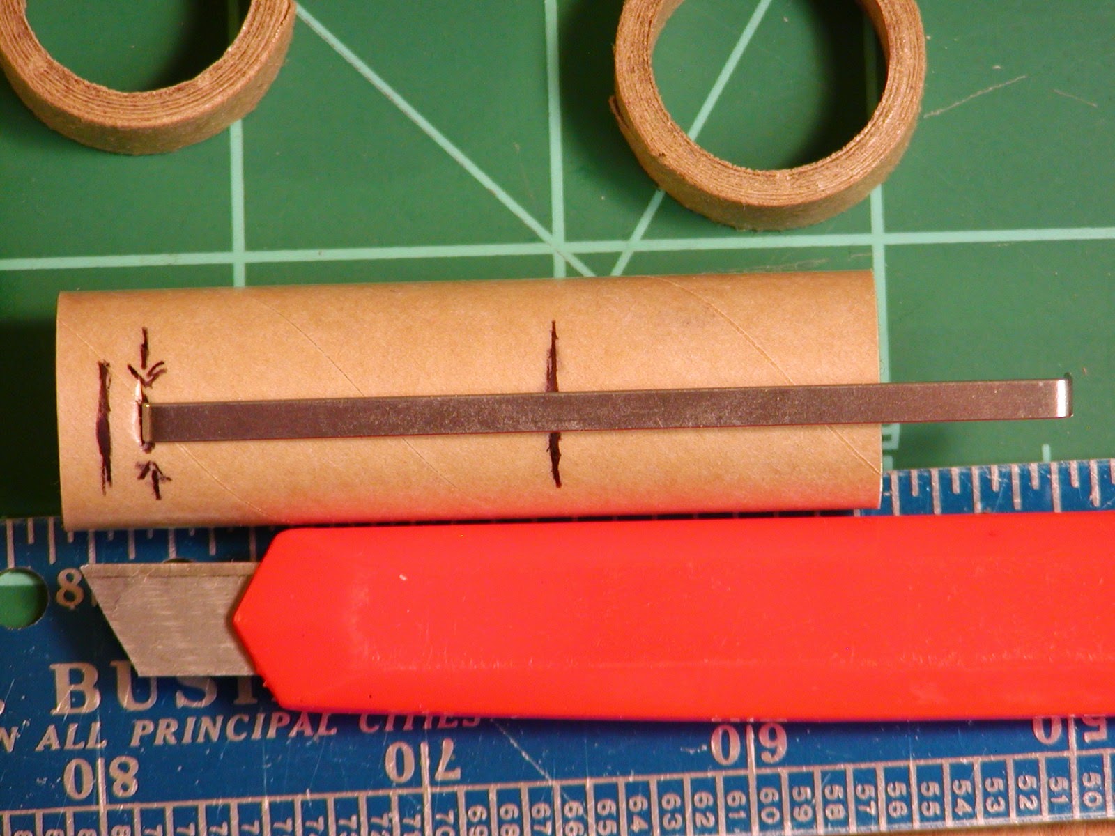
We will attach the top ring first, and as per instructions, it will be 1/8" (3 mm) from the top of the tube, covering the top of the clip. As for the second ring. The instructions call for it to be mounted so that the bottom of the ring is at 1" (25 mm). In our version, we will slide it up so that only the top is at that point.
 |
| The engine lock is not quite positioned straight here, but otherwise the mount is finished. |
There is a problem that seems to show up on some of these kits, and this one was no exception. The mounting rings are too small for the inside of the body tube. My solution was to cut a 1 5/8" (about 42 mm) by 7" (177 mm) and wrap this around both rings. I found that the glue stick was the best solution for getting this started, but you will want to use white glue on the rings themselves. Use the glue stick for the rest of the wrap.

Final Body Tube Assembly -
Back to the body tube. There will be some trimming needed to clean it up. My suggestion is the use a strip of paper about 2" (50 mm) wide. This paper needs to have a straight edge, and wrapped around the tube so that this edge is aligned, and then taped. Mark the tube at 11" (275 mm) from the "bottom", and slide our paper wrap to that point. Use a pen to draw a line around the tube along the edge of the wrap.

Once satisfied with the line (which should line up with the inner layers), use small scissors to remove the excess. Also trim the bottom of the body tube as needed, being sure to move the form as necessary. At this point, the tube is complete.

Make the marks for the positioning of the fins and launch lug as needed, per the instructions. Before they are attached, we will insert the completed engine mount. You will want to slide it in until the engine tube is flush with the bottom of the body tube. Use white glue for this, and make sure that you are fairly quick and steady as you insert the mount.

Fins & Patterns -
Before we move on to the fins, another recommendation. Rather than cutting the patterns out from the instruction booklet, I recommend photocopying that page, especially as the shock cord mount is on there as well. This allows the instruction booklet to be kept intact for reference later.
 |
| My all-in-one does color copies by default. |
It might look like the fin material (which appears to be a thick fiber or Bristol board) is insufficient for the three fins, but it is all really a matter of positioning the pattern.

Once the patterns were transferred, I cut the fins out with a razor knife. They can be cut with scissors, but be warned, this is some very tough material, and again I urge patience.
With the fins cut, construction proceeds as usual. To attach my fins, I used Aileen's Tacky Glue. First, I applied a thin bead of glue to the fin roots (where the notches are located). Then, I pressed the fin to their marked positions on the body tube, but removed them. Allow this glue to dry. This pre-glueing will ensure a stronger joint. Once the glue has finished setting, apply another bead of glue, this time not as thin, to the fin root again, and attach each unit again, making sure they are properly aligned and positioned.
Once the fins are attached, allow them to set. This is best done slowly. You might be able to insert the plastic tube again to hold the rocket while the fins set. When they have set, apply a bead of white glue to each side of the roots; these fillets not only help to reinforce the fin attachment point, they also help to streamline the rocket.

Finishing the Rocket; My Approach (Optional) -
Now, you can finish the rocket, following the rest of the instructions. Can the rocket be flown unpainted? Certainly. Since we inserted the engine mount prior to painting, we will paint the rocket using a different technique. Instead of using the plastic tube, I use rolled up newspaper to hold the rocket, though that is just a choice (I plan on reusing the tube). For my rocket, I applied a primer coat to allow for smoothing of the body tube.

Once that set, I smoothed it down with the back of a piece of fine sandpaper, basically polishing up the body (the fins were fine). Once I was satisfied with that, I applied a coat of gloss white.

This was allowed to set, and a final coat of high gloss dark red ("Robert's rockets are red") was applied, and my usual test pattern red/white checker board vinyl decal material used to decorate the rocket.

The final product is over 14" (350 mm) in length, and fairly light. On an A8-3, it performs very well, climbing easily to a couple hundred feet (around 60 meters). I imagine on a C class engine, it should put on quite a show.
Conclusion & The Pitsco "Model B" -
Hopefully, these little changes to this design should make this little rocket that much more durable. The hardest part of this kit is that body tube, and as I mentioned, we're going to discuss it. At some point, Pitsco made a version of this kit with a regular model rocket body tube. The finished body tube appears to be just about BT-52 in size. This version, one that I have dubbed the Pitsco Model B, no longer appears to be available. Certainly, it might just be as easy to buy a ready made BT-52 tube and go that route, and maybe in some situations that would be preferable. But for the price (currently just $5.95 USD), it's hard to compete against the Pitsco Model A. It may be challenging, but it has plenty of potential.
Thank you for posting such a detailed blog, especially after having the kit for almost 13 years! This link was shared with Pitsco's product development team. We're always striving to improve our products and appreciate customer feedback. We'd like to note that the latest version of this kit does have modified instructions and the parts have changed over the years.
ReplyDeleteRobert, we're interested in sending you the updated kit if you'd be willing to share your feedback of the latest version. If so, please email PitscoMarketing@pitsco.com with your shipping address and we'll make arrangements to get it to you.
Thanks again for all the great feedback!
Visit http://www.pitsco.com/Pitsco_Solid_Fuel_Rocket for more information. The Solid Fuel Rocket comes in two options: as a kit (product ID 13230) and as a 25-pack (product ID 51384).
Melissa,
DeleteThank you very much for the comment! Certainly going to take you up on the offer to evaluate a newer version of the kit (Going to tentatively designate it "Pitsco Model A-1").
One thing I really like about this rocket is how much it looks like those early kits from the late 1950's - early 1960's. I have a strong interest in model rockets from that era. And they were all very good flyers.
Thanks again!
no help
ReplyDelete